Tool Mentor: Creating a Software Architecture Document using SoDA
Purpose
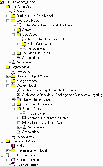
This tool guide describes how to use SoDA to create a Software Architecture Document. SoDA automates the generation of the report so that it is created quickly and accurately. The Software Architecture Document can be generated by SoDA either with the Word or Frame versions of the product. SoDA collects architectural significant aspects from a Rose model and adds those into the Software Architecture Document. This will only work if the Rose model follows the structure and naming convention for the Rose model.
Related Rational Unified Process Artifact: Software Architecture Document
Overview
This Tool Mentor is applicable when running Windows NT 4.0 or UNIX.
To create a The Software Architecture Document using SoDA, choose one of the following options:
- Using SoDA/Word to generate a Software Architecture Document
- Using SoDA/Frame to generate a Software Architecture Document
1. Using SoDA/Word to generate a Software Architecture
Document 
- From Rose, in any context.
- Select Report=>SoDA Report.
- From the list of available reports, select Rational Unified Process Software Architecture Document. If you do not see that report, cancel and make sure you have a use case selected in your class diagram.
- Click OK.
- Review the generated report.
2. Using SoDA/Frame to generate a Software
Architecture Document 
- From Frame, select File=>New. Click on SoDA, then RoseTemplates, then RationalUnifiedProcessSoftwareArchitectureDocument.fm.
- Edit the Connector and enter the name of the model file and the name of the use case.
- Use File=>Save As to save the template to a personal or project directory. You may wish to change the name of the template to reflect the name of the use case, such as ConductTransactionsReport.doc
- Select SoDA=>Generate Document.
- Review the generated document.
The next time you want to generate this same document, simply open the document and select SoDA=>Generate Document
3. Structure
and naming convention for the Rose model 
 |
The following diagrams are
extracted from the Rose model by the SoDA template and presented in the
appropriate sections of the Software Architecture Document:
|