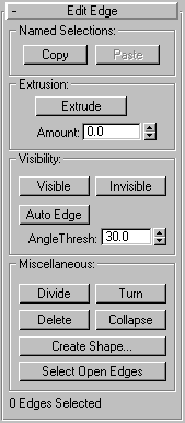

Lets you extrude selected edges. The edges appear as dashed lines. Works in a similar fashion to Face extrusion.
Extrude: Click, then either drag to extrude the selected edge(s), or adjust the spinner to perform the extrusion.
Amount: Set this to specify the amount to extrude the edge.
Sets the visibility of the edges. Invisible edges (also called construction lines) appear in the viewports when Edges Only is turned off in the Display command panel, or when you’re in Edge editing mode. The visibility of edges is primarily of importance when an object is being rendered using a wireframe material.
Visible: Makes selected edges visible.
Invisible: Makes selected edges invisible, so they won’t be displayed in Edges Only mode
Auto Edge: Automatically determines edge visibility based on adjacent edge angles, with the angle set by the Threshold spinner.
Angle Thresh: Set this to specify the angle threshold for the auto edge function.
.Divide: Divides the selected edge into two edges with a new vertex at the venter.
Turn: Rotates the edge within its bounding
Delete: Deletes selected edges
Collapse: Collapses selected edges by welding the vertex at one end of each selected edge to the vertex at the other end.
Create Shape: Creates a spline shape based on selected edges.
Select Open Edges: Click this to select all edges with only one face. In most objects, this will effectively show you where missing faces exist.
The Create Shape dialog appears.
The resultant shape consists of one or more splines whose vertices are coincident with the vertices in the selected edges. The Smooth option results in vertices using smooth values, while the Linear option results in linear splines with corner vertices.
When you region-select edges, all edges are highlighted, including hidden edges, which are displayed as dashed lines. As a default, the Create Shape function ignores the hidden edges, even though they’re selected. Uncheck the Ignore Hidden Edges item if you want to include the hidden edges in the calculation.
If the selected edges are not continuous, or if they branch, the resultant shape will consist of more than one spline. When the Create Curve function runs into a branching ‘Y’ in the edges, it makes an arbitrary decision as to which edge produces which spline. If you need to control this, select only those edges that will result in a single spline, and perform Create Curve repeatedly to make the correct number of shapes. Finally, use Attach in the Editable Spline to combine the shapes into one.