

Similar to the Editable Mesh is the editable spline. Most of the functions of the Edit Spline modifier become part of the editable spline. Once a single spline shape has been converted to an editable spline, most of its creation parameters are frozen and no longer available. However, its interpolation settings (step settings) remain available in the editable spline.
To produce an editable spline object, do one of the following:
Note: The Collapse utility, used to collapse mesh objects into a single, editable mesh, converts shapes to editable mesh objects rather than editable spline objects.
You can now directly animate vertices by simply turning on the Animate button while using Edit Spline, and then adjusting the vertex or its vector handles in the viewports. This lets you animate subobject portions of your shape at spline, segment, or vertex level.
When you animate any portion of a shape, three animation tracks are created for each animated vertexone describing the translation of the vertex, and the other two describing the translation of its handles.
Important: Observe the following caveats:
All of the functions in the editable spline are exactly the same as those in the Edit Spline modifier, with these exceptions:
At the object level are the following additions:
Attach Multiple: Works the same as in Editable Mesh. Click the Attach Multiple button to display the Attach Multiple dialog, which contains a list of all other shapes in the scene. Select the shapes you want to attach to the current editable spline, and then click OK.
Create Line: Adds more splines to the selected spline. Saves you having to return to the Create panel to draw lines.
The Interpolation area lets you adjust the number of steps in the shape, and specify the method by which the steps are calculated. It contains a Steps spinner, along with Optimize and Adaptive checkboxes. These controls work in the same fashion as the Interpolation controls found in the create parameters of any spline.
Lets you turn on and off the renderability of the shape, specify its thickness in the rendered scene, and apply mapping coordinates..

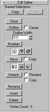
Close: Closes the selected spline by joining its end vertices.
Outline: Makes a copy of the spline, offset to the distance specified by the Outline Width spinner. You can adjust the outline position dynamically with the spinner. If the spline is open, the resulting spline and its outline will make a single closed spline.
Note: The algorithm has been changed to improve the result. To see the difference, create a V-shaped line. When you use the old Outline function, the width becomes narrower toward the crotch of the V. Using the new algorithm, the outline remains parallel.
Center: When this box is unchecked (default), the original spline stays still and the outline is offset on one side only to the distance specified by Outline Width. When this box is checked, the original spline and the outline both move away from an invisible center line to the distance specified by Outline Width.
Boolean: Combines two closed polygons by performing a boolean operation that alters the first spline you select and deletes the second one. There are three Boolean operations:
Union: Combines the two overlapping splines into a single spline, in which the overlapping portion is removed, leaving non-overlapping portions of the two splines as a single spline.
Subtraction: Subtracts the overlapping portion of the source spline from the target spline, and deletes the remainder of the source spline.
Intersection: Leaves only the overlapping portions of the two splines, deleting the non-overlapping portion of both splines.2D Booleans only work on 2D splines that are on the same 2D plane.
Mirror: Mirrors splines along the length, width, or diagonally. Click the direction you want to mirror first so it is active, then click Mirror.
Copy: If this box is checked, copies rather than moves the spline as it is mirrored.
Detatch: Copies selected spline(s) to a new spline object, and deletes them from the currently-selected spline if Copy is not checked.
Reorient: The spline being attached is moved and rotated so that its creation local coordinate system is aligned with the creation local coordinate system of the selected spline.
Vertex Count: Displays the number of vertices in the spline.
Reverse: Click this button to reverse the direction of the selected spline. If the spline is open, the first vertex will be switched to the opposite end of the spline. Reversing the direction of a spline is usually done in order to reverse the effect of using the Insert tool at vertex selection level.
Insert: This provides the same function as the Insert button in Vertex sub-object selection mode.
Delete: Deletes the selected spline.

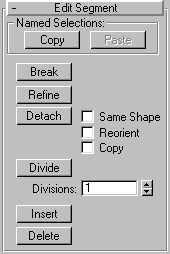
Break: Specifies a break point at any segment in the shape (you do not have to first select a segment). Click to turn on the Break button. The mouse icon changes to a Break icon You can now click on any spot on a segment. The clicked spot becomes two coincident vertices, and the segment is split into two parts.
Refine: Lets you click on any spot in a segment and add a vertex without altering the curvature values of the spline. Note that you don’t have to select a segment first, you can click anywhere on the shape.
Detach: Lets you select several segments in various splines and then detach them (or copy them) to form a new shape.
Reorient: The detached segment copies the position and orientation of the source object's creation Local coordinate system. The new detached object is moved and rotated so that its Local coordinate system is positioned and aligned with the origin of the current active grid.
Copy: Copies the detached segment rather than moving it.
Same Shape : When Same Shape is checked, the Reorient checkbox is disabled, and a Detach operation keeps the detached segment as part of the shape (rather than producing a new shape). If the Copy checkbox is also checked, then you end up with a detached copy of the segment in the same location.
Divide: This button, along with its associated Divisions spinner, lets you subdivide the selected segment into the number of division specified by the spinner. To use, select one or more segments, set the Divisions spinner, and then click Divide. Each selected segment is divided by the number of vertices specified in the Divisions spinner.
Insert: This provides the same function as the Insert button in Vertex sub-object selection mode.
Delete: Deletes any selected segments in the current shape.

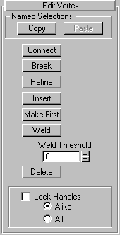
Connect: Connects any two end vertices, resulting in a linear segment, regardless of the tangent values of the end vertices. Click on the Connect button, point the mouse over an end vertex until the cursor changes to a cross, and then drag from one end vertex to another end vertex.
Break: This provides the same function as the Insert button in Vertex
Refine: This is a modal button that lets you click on any spot in a segment and add a vertex without altering the curvature values of the spline. Very useful for quickly adding extra control points to an existing segment.
Insert: Inserts one or more vertices, creating additional segments. After turning on the Insert button, click anywhere in a segment to insert a vertex and attach the mouse to the spline. Then move the mouse and click to add vertices. A single click inserts a corner vector, while a drag creates a smooth vector. Right-click to complete the operation and release the mouse
Make First: Specifies which vertex in the selected shape is the first vertex. Select one vertex on each spline within the currently-edited shape that you want to change. On open splines, it must be the endpoint that is not already the first vertex. On closed splines, it can be any point that isn't already the first vertex. Click on the Make First button, and the first vertices will be set. Once set, the first vertices appear with boxes around them.
Weld: Converts two end vertices, or two adjacent vertices within the same spline, into a single vertex. Move either two end vertices or two adjacent vertices near each other, select both vertices, and then click on Weld. If the vertices are within the unit distance set by the Weld Threshold spinner, they’re converted into a single vertex. You can weld a selection set of vertices, as long as each pair of vertices is within the threshold.
Delete: Deletes the selected vertex or vertices, along with any segments in between
Lock Handles: When you select one or more vertices, vector handles appear on those vertices with smooth values. By default, dragging either handle moves both handles. SHIFT-click a handle to "break" the tangent and move each handle independently.
Alike: As you drag the handle of an incoming vector, all incoming vectors of the selected vertices move simultaneously.
All: Any handle you move affects all vectors in the selection, regardless of whether they’re broken. You can use All with a single vertex. As you move either handle, the adjacent vector