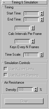


The controls in this rollout let you specify the range included in the calculation. Other controls in this rollout let you specify how IK is included in the simulation, and what the air density is for the simulation.
The controls in this rollout control how the keys are generated over time.
Start Time: Specifies the first frame to generate a key, and the first frame to be considered for the solution.
End Time: Specifies the last key generated for the simulation. Note that this spinner is set to the last frame of the active segment when you create a new simulation. For example, if your active segment ends at frame 200, when you click New to create a new simulation, the End Time is set to 200.
Calc Intervals Per Frame: Specifies how many calculations are performed for each frame of the simulation time range. You can increase this as high as one calculation per tickthough that would definitely be overkill. Finding the right number for this spinner is a matter of experimentation. As a general rule, the faster things are moving in the simulation, the higher you should set this value. If things are supposed to move slowly and ponderously, you can set this to 1.
Note: If you find that objects are not colliding properly with other objects (they’re going through them), increase the Calc Intervals Per Frame value.
Keys Every N Frames: Specifies the frequency with which keys are generated, per object. Thus, if this were set to 2, keys would be generated on every other frame.
Time Scale: Generally, this value lets you slow down or speed up the overall effect of the simulation. It does this by applying a linear scale factor to the outside forces affecting each object (gravity, wind, and so on). The default value of 1 results in normal speed. You can scale down the simulation (make it slower) by using values below 1 (from 0.1 to 1), and you can scale up the simulation (make it faster) by using values greater than 1 (from 1 to 100). As is always the case, if you speed up your simulation and objects begin to behave incorrectly (going through objects, for example), increase the Calc Intervals Per Frame value to compensate.
Controls in this area relate to IK settings and the transfer of momentum.
Use IK Joint Limits: When checked, the current IK joint limit settings are used as constraints by hierarchies in the simulation.
Use IK Joint Damping: When checked, the IK damping settings are used as constraints by hierarchies in the simulation.
Density %: Sets the air density in the simulation. A setting of 100 is the air at sea level. A setting of 0 is a total vacuum. When anything moves, it hits air resistance (except in space). The faster it moves, the higher the relative air resistancewith the square of the speed. Thus, air resistance imposes an upper limit on the speed of things that are falling with gravity, and also makes objects tumble due to the effect of air resistance on each face of the object.
Close: Click to close the Dynamics utility.

Edit Object List Dialog: Click this to display a dialog that lets you specify which objects in the scene will be calculated as part of the simulation. The dialog functions in the same way as the lighting Exclude dialog, so its components are not described here. Basically, you highlight objects from the Objects in the SCENE list window at left, and then click the > button to place them in the Objects in the SIMULATION list window at right. The Exclude and Include option buttons above the rightmost window determine whether the items listed are excluded or included in the simulation.
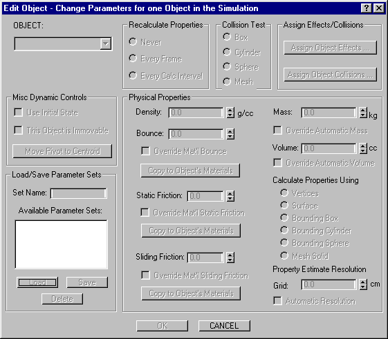
Edit Object Dialog: Displays a dialog that lets you set dynamic properties for any object in the simulation. This is the dialog in which you’ll spend most of your time setting up your dynamics simulation.
Object: Displays the name of the object for which you’re setting the dynamic properties. All settings in the Edit Object dialog affect the object listed here. To change the object you’re affecting, open the pop-up list, and choose from a list of all objects assigned to the simulation. (Objects are assigned to the simulation using the Edit Object List dialog, described in the previous section.)
The options here let you choose if you want to recalculate the properties of an object that changes over the course of the animation. Specifically, the properties refer to the mass moment of the object. The mass moment of an object can be defined as the measure of how the mass in an object is distributed with respect to the center of mass of that object. Altering the mass moment changes the way an object responds to torque. For example, a spinning ice skater can alter her mass moment, and thereby increase her spin, by pulling her arms in toward her body. Thus, if your object is changing shape over time, and you want to take this into account for the simulation, you should recalculate the properties.
Never: No calculation is performed, beyond the first calculation for the dynamics solution.
Every Frame: The object’s properties are recalculated for every frame.
Every Calc Interval: The object’s properties are recalculated at each “Calc Interval.” The Calc Interval (interval of calculation) is set in the Time Parameters rollout, and specifies how many calculations are performed for each frame of the simulation time range.
The options in this area specify which type of boundary is used for collision testing.
Box: A bounding box is used to test collision. This is the fasted method. If your object is a box or close to a box shape, this option is both fast and accurate.
Cylinder: A cylindrical form is used to test collision. The “height” axis of the cylinder is aligned with the local Z axis of the object.
Sphere: A spherical form is used to test collision.
Mesh: Uses the surface of the object to calculate the collision. This option is the most accurate, but also takes far longer to calculate than the previous three methods. Use this only when your object is too complex to work properly with the first three options.
Provides two buttons that display subdialogs letting you specify which effects in the scene will affect the current object, or which objects in the scene can collide with the current object.
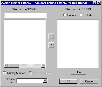
Assign Object Effects: Click to display a subdialog that lets you specify which effects in the scene will affect the current object. The dialog consists of two list windows. All effects in the scene are listed in the window at left. Highlight from the list, and then click the > button to transfer the highlighted effects to the window at right.
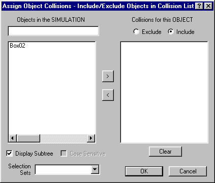
Assign Object Collisions: Click this to display a subdialog that lets you choose which objects in the scene are considered for collision with the current object. This dialog works the same as the Assign Object Effects dialog, except that it lists only the objects that are in the scene. Objects included for collision in this dialog can collide with the current object.
Use Initial State: When this is checked, the simulation solves for the motion, energy, and momenta of the object at the input time for the simulation. (The frame specified in the Start Time spinner in the Time Parameters rollout.) If Use Initial State is unchecked, the object is assumed to be sitting motionless at the input time for the simulation. The Dynamics utility overwrites keys, and it can’t deal with things moving through the simulation without specific keys, so either the object’s keys are clocked with the simulation, or it’s not moving (or both). Thus, if you don’t solve for the initial state, the object’s keys are interpolated at the instant the simulation starts and all subsequent motion comes from the interaction of the simulation itself.
This Object is Immovable: When this is checked, the object will not move throughout the simulation. Its mass and inertia are infinite, and it cannot be affected by anything that collides with it.
Move Pivot to Centroid: When this button is on (green), and you exit the Edit Object dialog by clicking OK, then the object’s pivot point is moved to its center of mass. Having the pivot aligned with the center of mass speeds up the dynamics calculation, and makes manual keyframing of the objects appear more natural. However, if the pivot point is already positioned as part of a linked hierarchy, doing this will alter the positioning of your hierarchical linkage.
Lets you save the current Edit Object parameter settings, or load previously saved parameter settings. Among other things, you can use these controls to save the settings for one object, and then apply them to another object. To save the settings, enter a name in the Set Name field, and then click the Save button. The saved parameters appear in the list window. To load previously saved settings, highlight a name in the list window, and then click the Load button. To delete saved parameter settings, highlight a name in the list window, and then click Delete.
Set Name (edit field)
Available Parameters Sets (list window)
Load (button)
Save (button)
Delete (button)
Provides a number of controls that specify the physical properties of the current object.
Density g/cc: Specifies the density of the object in grams per cc. A setting of 1 is the equivalent of water, and good for anything wooden, plastic, or organic. The more dense an object, the slower it will react to forces. There is a direct relationship between Density and Mass, so when you alter the Density, the Mass value changes (when it’s automatic value is not overridden).
Static Friction: Static friction specifies how hard it is to start moving on a surface. The value used for static friction is taken from the Dynamics Properties of the material assigned to the object, and this spinner is disabled unless Override Mat’l Static Friction is checked.
Override Mat’l Static Friction: Check this to enable the Static Friction spinner when you want to use a specific value that’s different than that assigned by the object’s material. Note that, when using a Multi/SubObject material, you can assign different static friction values to the submaterials, and thus to different faces of an object. But if you use an override value, it affects the whole object only.
Copy to Object’s Materials: Check this and, when you exit the Edit Object dialog by clicking OK, the value in the Static Friction spinner is copied to the top level of the material assigned to the object.
Sliding Friction: Sliding friction determines how hard it is for an object to keep moving over a surface. These settings are also taken from the Dynamic Properties of the assigned material. The associated checkboxes work in the same way as well.
Bounce : Specifies how much the object bounces after collision. These settings are also taken from the Dynamic Properties of the assigned material. The associated checkboxes work in the same way as well.
Mass : Technically, mass is the measure of how many subatomic particles are in an object. In 3DS MAX, it’s calculated as a result of density times volume. Practically speaking, mass can be described as the resistance to acceleration given a constant force. The greater the mass, the more resistance. Note that this value (when not overridden) is derived from the Density and Volume, and that Volume (when automatically calculated) is affected by the Calculate Properties Using options.
Override Automatic Mass: Check this to enable the Mass spinner so you can specify your own mass value. When you override the automatic value, the Mass value is no longer affected by the Density or Volume values.
Volume cc: This is the volume of the object, measured in cubic centimeters. When automatically calculated, this value depends on the option chosen under Calculate Properties Using.
Override Automatic Volume: Check this to enable the Volume spinner so you can specify your own mass value. When you override the automatic Volume value, it’s no longer affected by the Calculate Properties Using options, and it no longer affects the Mass value.
Calculate Properties Using: The options in this area let you specify what type of geometry the simulation will use to calculate the mass, the volume and the mass moment. When the Mass and Volume values are automatically calculated (their Overrides are unchecked), changing these options affects the Volume, and therefore the Mass values. This dialog works the same as the Assign Object Collisions dialog, except that it lists only the effects that are in the scene.
Vertices: When this is chosen, the object is treated as a “point cloud,” or a collection of vertices without segments. Each vertex is given a mass of 1 gram, but the object itself has no volume.
Surface: This option treats the object as a hollow shell whose thickness is 1 centimeter. The mass is derived from the surface area and the 1-centimeter thickness, but the object has no volume.
Bounding Box: A bounding box surrounding the extents of the object is used to calculate both the volume (of a solid bounding box) and the mass (based on the volume).
Bounding Cylinder: Similar to the Bounding Box option, except that a bounding cylinder is used, whose Z height axis is aligned with the local Z axis of the object.
Bounding Sphere: Similar to Bounding Box, except that a bounding sphere is used.
Mesh Solid: The geometry of the object is used to calculate both the volume and the mass.
Property Estimate Resolution: The items here become enabled only when the Mesh Solid option is chosen, and affect the accuracy with which the mass moment is calculated. This, in turn, determines how accurately the rotation of the object responds to torque.
Grid cm: A sampling grid is used to calculate the mass moment. The smaller the cells in the grid, the more accurate the calculation. The grid cells are measured in centimeters, regardless of the current display unit.
Automatic Resolution: Check this to let the Dynamics utility automatically set the grid size based on the complexity and size of the object. In addition, when you check this, the lowest value that will be automatically calculated is plugged into the Grid spinner (which is also disabled). Thus, if you want to specify your own grid value using the Grid spinner, but want some idea of where to start, you can check and then uncheck Automatic Resolution.
Click to display a dialog that lets you specify which effects will globally affect all objects in the simulation. The dialog is the same as the lighting Exclude dialog, so its components are not described here. All available effects appear in the list window at the left of the dialogs. Select the effects from that list window, and then click the > button to place them in the Effects on all OBJECTS window at right.

Click to display a dialog that lets you specify which objects in the simulation are globally considered for collisions in the simulation. This dialog works the same as the Assign Global Effects dialog. The list window at left lists all of the objects in the simulation. Choose the objects from that list, and click the > button to place them in the Objects in the COLLISION LIST window at right.
