Battlecraft
1942 2.0 UsersÆ Guide
Written By Tom Benson,
Ian Blas, David Higuchi, and
This
guide is provided as the comprehensive guide to the features available in
Battlecraft 1942.áá Battlecraft 1942 is
an unsupported product.á Electronic Arts
will not provide technical support, via email or phone, for this product.á
For
version release notes, please consult the readme.
Table of Contents:
- Installing
- Starting Battlecraft 1942
- Creating a map
- Saving and loading
- Surface Map Assignments
- The Camera
- Terrain View Modes
- Mapper Modes:
- Terrain Mapper (Terrain Editor)
- Material Mapper (texture and material
mapper)
- Surface Map Painter
- Object Mapper (static object placement
and modification tool)
- Control Points, Soldier Spawn points,
and Object spawn points
- áStatic Objects
- áLight,
Fog, and Shadow
1. Installingù we recommend you install
Battlecraft 1942 to the default installation folder.á All information in this document assumes you
have done so.
2.A.
When starting Battlecraft
1942, the User is asked to select their mod (or create a new one). Note, that
when starting Battlecraft 1942, the Mod ôbf1942ö is not created. The User must
click on ônewö and create it in order to be able to create maps for BattleField 1942. After making their selection, a popup
screen with the option to open an existing level, create a new level, or exit
the program comes up.á After ôopenö or
ônewö is selected, you must select the mod you wish to use for the level.áá "Edit Mod Settings" comes up.á It defaults to C:\Program Files\EA
Games\Battlefield 1942\.á If you have a
non-default installation of Battlefield, make sure that this is pointed in the
right place. If you are using a Mod, you MUST edit the path in the appropriate
.cgf file located in the Battlecraft 1942 1942 program folder to point to the proper Mod.
2.B.
If you want to use the original Battlefield levels, make sure you use
the mod named BF1942.á áNote:á
The original Battlefield 1942 levels contain many differences from
Battlecraft 1942 created maps.á If you
open an original map and save it, you will not be able to play that map online.
3.A.
When creating a new map, the following screen appears:
 á
á
Figure 1: New level
Menu
Setting
the Beginning Level Attributes
3.B.
The Level Size button does not actually make larger or smaller
levelsùit just defines the in-bound area.á
This is consistent with the way the actual Battlefield 1942 levels work.
3.C.
The Height Scale slider determines the base height of the level
(i.e. how far away from sea level)
3.D.
The Theatre determines which variety of vehicle and soldier
skins are used.
3.E.
The Random Map Generator leads to a further screen:
3.F.
 á
á
Fig 2:
Random Terrain Generation Menu
3.F.1.
The smoothness scale goes from least smooth on the left
side to most smooth on the right.
3.F.2.
The height scale goes from lowest on the left to highest on
the right.á
4.A.
After creating a level, the program does autosave it at creation.á
4.B.
áIf you wish to
change the name of the level, you canÆt. However, you can ôCopy Level toö to
save the exact level under a different name.
4.C.
áWhen Loading a level, select ôOpen levelö (or Ctrl+O).
You will be asked which mod to load a level from. Select the Mod where the
desired level is saved, then open.
4.D.
áA handy bunchy of tips now display at startup.á These cannot be deselected until you have
read (or at least scrolled through) all of them.á We advise reading them.
4.E.
There is a ôcopy toö function.á This function copies the level to a new
level, named however you wish.á
5.
Surface Map Assignmentsá NB:á Note: Until you
create surface maps, the terrain will remain gray. After surface maps are
created, you will be able to see which texture is placed where in all mapper
modes, not just material mapper mode. To generate surface maps, click the
ôSurface Map Assignmentsö button.

Figure 3: Surface Map
Assignments button
5.A.
Click on Surface Map Assignments above, to get to
this screen:

Figure 3: Surface Map
Assignments menu
5.B.
By clicking on the blue squares, you can assign the squares that will
have surface maps operable on them. The texture sets available are default,
desert, and snowy.
5.C.
The red boxes are the offset buttons, which are used to delineate
the playing areaùif you want a smaller map size, like
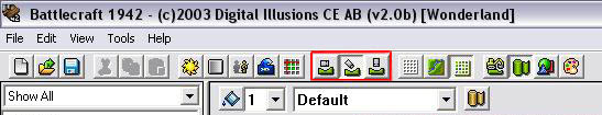 Figure 4: the
Camera tools.
Figure 4: the
Camera tools.
6.A.
áThatÆs a screenshot of the
toolbar.á Right now, weÆre just focusing
on the three buttons outlined in red û The camera views.
6.B.
The three
buttons control camera angle.á The first
sets the camera angle parallel and close to the surface.á This is called On Terrain Mode (I).á The second sets it at an approximately
45-degree angle to the surface.á This is
called Camera Fly Mode (O). The third gives a direct birds-eye
view.á This is called Top-Down Mode (P).
6.C.
áIn addition to these buttons, holding
down the right mouse button and moving the mouse can control the camera
angle.á This causes the camera to rotate
around a fixed point.á The altitude of
the camera cannot be altered when it is in Terrain Mode.á The camera position can be zoomed in or out,
or moved left, right, up, or down when it is in Top-Down Mode.á
6.D.
The camera is moved around the map using the arrow keys.á Holding downá the Shift key will speed up the
movement of the camera.

Figure
5:á Terrain View Modes.
7.A.
áThe terrain view mode buttons are,
reading left to right, Wireframe Mode (J),
Textured Surface Mode (K), and Textured Wireframe Mode (L).
7.B.
Note that these view modes have no effect on viewing objects.á They only change the way you look at terrain.
7.C.
The functions of
each are pretty self-explanatory:á Wireframe shows the terrain in solid wireframe without any terrain textures, Textured Surface
shows the textured surface of the level, which defaults to a funky
yellow-and-brown if no textures have been laid out
yet.á Textured Wireframe,
pretty obviously, has the terrain textured surface with a wireframe
laid over it.
7.D.
NOTE:á The above is true if you are in the Terrain
Mapper, Object Mapper, or Surface Painter, not in the Material
Mapper (see below), which shows the actual material (sand, grass, etc.)
labeled on the surface OR a simplistic graphical representation of the
textures.
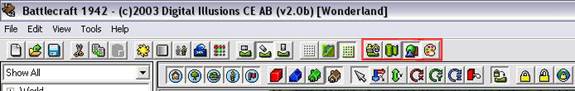
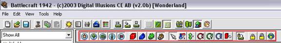
Figure 6: Mapper Modes
8.A.
áThe above shows
the location of the Mapper buttons.á
These are used to switch between altering terrain (as in raising and
lowering terrain), altering material (as in grass, sand, etc.) altering objects
(adding, removing, moving objects such as houses, trees, bunkers, etc, and
altering the look of the surface (editing the terrain, but not changing the
actual laid out terrain)
8.B.
áReading from left
to right, the buttons are the Terrain Mapper, Material Mapper, Object
Mapper, and Surface Map Painter.á
Their functions are as described above.á
However, clicking on any of them alters the toolbar in significant ways,
so weÆll be covering them as a topic for a while.
8.C.
VERY IMPORTANT
NOTE:á When in Material, Terrain
Mapper, and Surface Painter modes, the TAB key switches between having
objects visible and having objects hidden.
8.D.
áUndo is
functional in all mapper modes except Surface Map Painter mode. Undo will
function on every change you have made to an object.á Note: There is no ôredoö function.á
8.E.1. The Terrain Mapper has the following toolbar items associated with
it:

Figure
7:á Terrain Mapper Tools
8.E.2. Reading
from left to right, these buttons are the Point Manipulation Tool toggle (Z), the Point
Auto-Smoothing toggle (X), and the size modifier for the auto-smoothing.
8.E.2.a.
The Point Manipulation Tool is one of
the trickier tools to master, but quite useful.á
Basically, you click on various points (the intersections of the
gridlines in wireframe view) and adjust their height
by either pressing plus and minus or by holding shift down and scrolling the
mouse up and down.á Holding down Ctrl
allows you to ôpaintö manipulation points wherever you drag the mouseùuseful
for when you want to cover a large area quickly.
8.E.2.b.
Point Auto-Smoothing changes the area affected by
the Point Manipulation Tool from a single point, to a point with a
radius. Note: The Radius is changed by using the drop down menu located to the
right of the Point Auto-Smoothing toggle
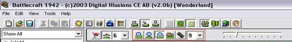
Figure 8. The
terrain manipulation tools
8.E.3. The next
four buttons, with the blue ball above the green terrain, are for lowering,
raising, smoothing, and flattening (i.e. bringing up or down to a certain
level) the terrain.á
8.E.3.a.
Carving Tool- This tool allows you to lower, or create indentations in the terrain.
Simply move the mouse pointer to the desired area and click or hold down the
left mouse button to carve. To adjust the speed at which you carve, click and
drag the Intensity Bar.
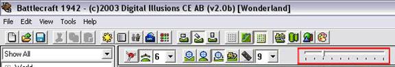
Figure 9: The intensity
bar
You can also increase or decrease the size of the affected
area, by changing the size number in the Drop Down menu.

Figure 10: The sizing
menu.
8.E.3.b.
Raising Tool- This tool allows you to raise the terrain to a desired height. This
tool is useful for making mountains, etc.á
To raise terrain, move the mouse pointer to the desired area and click
or hold down the left mouse button. Again, you have the option to increase or
decrease the size of the affected area, by changing the size number in the Drop
Down menu and change the speed at which you raise the terrain by adjusting the
Intensity Bar.
8.E.3.c.
Smoothing Tool- The
Smoothing Tool allows you to smooth out any jagged points that might appear on
your terrain.á To use the smoothing tool,
place the mouse indicator over any jagged points or edges and click the left
mouse button. You can also smooth out large areas of terrain by holding down
the left mouse button and moving the mouse over the desired area.
8.E.3.d.
Flatten Tool- The
Flatten Tool allows you to instantly level any area of the terrain with a click
of the mouse. To use, set the square to the desired size, then move the mouse over
to the area that needs leveling, and click the left mouse button. For large
areas, you can click and hold the left mouse button.á In order to set the level to which the
leveler levels, hold Ctrl and click on a piece of terrain that is at that
level.
8.E.4. The Road Tool is another quite useful
tool.áá In order to use it, you hold Ctrl
while clicking along the path that you want the road to take.á When you release Ctrl, you will be prompted
to determine the size of your road and whether or not you want to add material
(dirt, mud, etc.) to it.
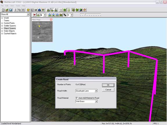
Figure 12: Using the
Road Tool
One thing to remember here is that the
road tool does not carve a straight path from point to pointùit tries to smooth
the road in with the surrounding terrain.á
So if you put a path over a mountain, itÆs not going to be drivable
unless youÆve taken the time to smooth it out first.áá So, even with the very moderately bumpy
terrain above, the road featured would look like this:

Figure
13:á After Using the Road Tool
8.F.
The Material Mapper button allows you to lay down surface
textures such as grass, sand, and water.
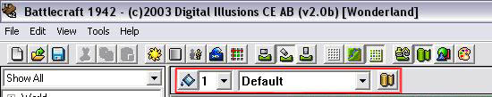
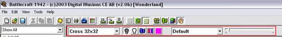
Figure 14:
The Material Mapper Tools
8.F.1. The tools
are, reading left to right, Fill With Material, which fills the selected
area with material of the selected type (defaults to the entire map if the
Marquee Tool is not used) Size Drop Down Menu- Increases and decreases the size of the painting area, Texture
Drop Down Menu- This drop down menu, allows you to select the different
type of textures to place on top of the terrain, Toggle Surface View-
This tool allows you to toggle between the two surface views.á One view shows each square on the map with a
text description of the texture used while the other, shows the actual textures
on the terrain.


Figure 15:
The
8.F.2. Important Note: After you finish laying down textures, you must click
on Generate Surface Maps to see textures in
game. To do so, click Tools > Generate Surface Maps.

Figure 16: How to
Generate Surface Maps
And of course this only is going to work if
youÆve correctly followed the steps outlined under section 5 above regarding
surface map assignments.
8.F.3. After youÆve done this, the textures will be smoothed out
and meshed into themselves.
8.G.
áThe Object Mapper allows you to add cached
objects such as structures, props, and vegetation to your map
Figure
17: Views and Tools Available For The Object Mapper
8.G.1.The first five buttons determine which objects are shown
while using the Object Mapper.á They are,
from left to right, Show
Standard Meshes- Toggle structures (buildings, props, etc.) on
or off. Show Tree Meshes- Toggle vegetation on or off. Show Object
Spawns- Toggle object spawn points on or off. Show Soldier Spawns-
Toggle solder spawn points on or off. Show Control Points- You guessed
it! û Toggle control points on or off.
8.G.2.The
next four buttons determine how objects are viewed.á From left to right, the views are View as Bounding Box- this shows the actual area the object
occupies, and is the best way to check if two objects are intersecting. as Collision Mesh- this shows the lines of object collision, for
vehicles and objects attempting to pass through. View as Detail Mesh- this
shows the objects in solid color rather than textures.á This view makes it a lot easier to see
exactly where all of your objects are in relation to each other.á View as Textured Mesh- This
view allows you to see all cached objects in full detail with textures on.
8.G.3.The
next (and last) buttons show the object manipulation tools:

Figure 18: Object Manipulation Tools
8.H.
áThe Surface Map Painter allows you to æpaintÆ over an existing
surface
Figure
19: Surface Map Painter Tools
8.H.1.
8.H.2.None of these tools
actually paint the materials-- the sound a soldier stepping on an area of
"wet grass" material that has had "rock surface" painted on
it will still make the "wet grass" sound. Whatever terrain is shown
in the Material Mapper Mode is the actual material placed.
áá
9.
Control
Points, Soldier Spawn points, and
Object spawn points.
9.A.
At first glance, the tools used to govern these seem complicated, but
since they all work in relatively the same way theyÆre basically easy to get a
grip on.á First of all, theyÆre all
contained in a tree hierarchy on the left side of the Battlecraft 1942 GUI.

Figure 20:á The Level Tree and Control Points
9.B.
The ôShow All/CQ/CTF/TDMö drop-down menu can be used to show where the
Control Points, Object and Soldier Spawns are in the different map modes.

Figure 21:á Game Type Display Changing
9.C.
Control points, soldier spawns, objects,
and objects spawns are all moved using the object manipulation tools that were
described in section 8.F.4 above.á
9.D.
The Control points section is used for the placement of new and modification
of existing control points.á Every level,
by default, starts out with two Main Bases, one for each side.á These each have one
default Soldier Spawn apiece.á
9.D.1.In order to place down new Control Points,
click on Drag New Control Point and drag onto the map.á A new control point will pop up where youÆve
dragged it.á
9.D.1.a.
In order to alter the properties of a control point, either
double-click it in the tree hierarchy or just double-click the control point
object itself.á This will bring up the
following screen:

Figure 22:á Control Point Edit Screen
9.D.1.a.1.
Most of these values are pretty easily understood.
9.D.1.a.2.
Name and ControlPointName modify the name
youÆre calling it and the name it will show up as in game.
9.D.1.a.3.
Radius changes the radius around the control pointùas in the radius
within which you need to be to change control.
9.D.1.a.4.
Team changes which team the CP starts out belonging too.
9.D.1.a.5.
AreaValue is the way
to make ticket bleed function correctly.á
Basically, whichever team has 100 or more area value points starts
ticket bleed for the other team.á So, if
you have three points, two non-capturable bases and a
neutral point, if you assign each point an area value of fifty, whoever holds
the neutral point causes the other team to begin bleeding.
9.D.1.a.6.
TimeToGetControl is the time from when the flag goes grey to when a
soldier within the radius is able to capture it for his team.
9.D.1.a.7.
Likewise,
TimeToLoseControl is the time it takes to turn the
flag to gray when it currently belongs to a team and an enemy soldier is within
the radius.
9.D.1.a.8.
DisableIfEnemyInsideRadius is a binary value that determines if an enemy alone is
inside the radius of the flag, the spawn points associated with that flag wonÆt
function.
9.D.1.a.9.
áDisableWhenLosingControl
is a binary value that determines that the point no longer functions as a spawn
when the flag is contested.
9.D.1.a.10. áLoseControlWhenEnemyClose is a binary value that determines
whether or not this flag is capturable by the enemy.
9.D.1.a.11. áLoseControlWhenNotClose is a binary value that determines
that if a member of your team is not near this flag, it will revert to gray.
9.D.1.a.12. áUnableToChangeTeam is a binary value that determines ONLY
if the flag appears as a non-capturable map on the minimap.á It does not
actually affect whether or not the base is capturable.á
9.D.1.a.13. áGeometry is a
very nifty function.á Basically, the
geometry (object) of the flagpole can be anything, from a rock to a house to a
leaf.á This is where that is set.á Example:á
bclas_m1
9.D.1.a.14. áHasCollisionPhysics is a binary value that determines
whether or not the object specified by Geometry has collision physics.
9.D.1.a.15. áAddTemplate is the area where the animation for the flag is
stored.
9.D.1.a.16. áTeamGeometry 1:á governs
which flag is used for Team 1ùBC automatically sets this for the correct flag
for the team selected in Teams, but if you want to change it, either to a
personally created flag or just to another standard flag, this is where that is
altered.á Example:á flagjp_1
9.D.1.a.17. áTeamGeometry 2:á
governs which flag is used for Team 2ùBC automatically sets this for the
correct flag for the team selected in Teams, but if you want to change it,
either to a personally created flag or just to another standard flag, this is where
that is altered.á Example:á flagjp_1
9.D.1.a.18. áRelative
position appears not to have any effect.
9.D.1.a.19. áPosition gives
the coordinates that the control point is atùadjusting these coordinates moves
the flag accordingly.
9.D.1.a.20. áGame modes
govern which game modes the control point actually appears in.
9.D.1.a.21. áFlag is a CTF
Capture point governs whether this control point functions as a takeable flag during Capture the Flag games.
9.E.
In order to place down new solder spawns, click on Drag New Soldier Spawn and drag onto the map.á New soldier spawn will pop up where youÆve
dragged it, and automatically attach itself to a base.

Figure 23:á Soldier Spawn Edit
9.E.1. If a spawn point is double clicked, the Edit Soldier Spawn menu
appears.á
9.E.1.a. The Name value changes only what the name of the spawn
point is inside BCùit has no affect on gameplay.
9.E.1.b. The Spawn Group drop-down menu attaches the spawn point
to a particular base.á This defaults to
the first placed base on the map.
9.E.1.c. Spawn ID simply provides another identity for the
spawnùit has no in-game function and should not be altered, except if you want
to be very organized about your spawn pointsùin other words, if you create four
spawn points for one control points, four for another, delete the first one,
and then create four more for another, the first new spawn point that you put
down will have SpawnID 1.á This will have no bad affect on the map.
9.E.1.d. SpawnAsParaTrooper is a binary value governing whether or not the
soldiers spawn in with their chutes open.á
Of course, if the point is on the ground, this is a severely moot point
9.E.1.e. Pos gives the coordinate
location of the spawn point.
9.E.1.f.
ááááááRot gives the rotation angle of the
soldier as he spawns inùthe only value that really matters here is the X axis
portion, because the soldier will automatically flip vertically straight after
spawning in.
9.E.1.g. Game Modes governs which game modes the Spawn Point is
active under.
9.F.
Object Spawns
work somewhat differently than control point and soldier
spawns, but have many things in common.
9.F.1. In order to create a new object spawn, you must first
double-click on the Add Template section in the Level Tree.á This will
bring up the Edit Object Spawn
Template menu.

Figure 24:á Object Spawn Template Screen
9.F.1.a.
áááááThe values here will govern
all object spawns that use this particular template.
9.F.1.b.
The Name value is only an internal BC functionùit changes what the
template (and all associated object spawns) is called in the Level Tree.
9.F.1.c.
áááááTeam 1 Object is a dropdown
menu of all spawnable objects.á It selects what object spawns for team 1, if
team 1 controls the object spawn.
9.F.1.d.
Team 2 Object is a dropdown menu of all spawnable
objects.á It selects what object spawns
for team 2 if team 2 controls the object spawn.
9.F.1.e. ááááááMinSpawnDelay is the minimum amount of time between the
spawned object being destroyed and the spawning of a new one.
9.F.1.f.
ááááááMaxSpawnDelay
is the maximum amount of time between the spawned object being destroyed and
the spawning of a new one.
9.F.1.g. SpawnDelayAtStart is how much time from the beginning of a map it takes
the object to spawn.
9.F.1.h. TimeToLive is how much time passes before an abandoned vehicle
from this object spawn (i.e. unoccupied, moved from the original spawn) begins
taking damage.
9.F.1.i.
ááááááDistance is how far the vehicle can be
from its original spawn before the TimeToLive
countdown starts.
9.F.1.j.
ááááá
DamageWhenLost is the amount of damage the vehicle takes per second
while lost.
9.F.1.k. MaxNrOfObjectSpawned governs the number of individual vehicles that can be
produced by this object spawn point.
9.F.2. ááAfter a template
has been created, it is added into the Level Tree.

Figure 25:á Object Spawn Templates in the Level Tree
9.F.3.
In order to place an object spawn, drag the correct template onto the
map.á This will create a new object spawn
with the settings specified in the template.á
It will also display the hull of the vehicle.
9.F.4.
Note that unlike soldier spawns, object spawns do not default to
belonging to any control point.á This is
so that you can make object spawns that spawn vehicles independent of control
points (like the airfield on Gazala.)
9.F.5. Double clicking on the object spawn while using the
select tool in the Object Mapper, or just double-clicking on the specific entry in the Level Tree, brings up the Edit Object Spawn submenu.

Figure 27:á Editing Individual Object Spawns
9.F.5.a.
ááááááMost of the values here are
reasonably obvious.
9.F.5.b.
Pos are the coordinates that the spawn is placed at.á Changing these numbers changes the position
of the spawn.
9.F.5.c.
ááááááRot is the angle the vehicle spawns facing.
9.F.5.d.
OsID is the way to link the object spawn to a
particular control point.á If it is not
linked to any control point, it will spawn vehicles constantly, according to
the template rules.
9.F.5.e.
ááááááTeam governs which type of vehicle spawns at the
start of the map, the Team 1 object or the Team 2 object.
9.F.5.f.
áááááGame mode governs which game modes the
object spawn is active in.
10.A.
Static objects are placed in a way similar to the placement
of object spawns.á First they have to be
cached, and then they can be placed.
10.B.
When Add a New Object is double-clicked, the Object
Browser submenu comes up.

Figure 28:á Static Object Browser
10.B.1.
ááááááBy scrolling through the
objects, the user is given a preview in the main BC window.á
10.B.2.
ááááááThe filter
works.á If you type ôtreeö in it, only
objects with ôtreeö in their title appear.
10.B.3.
ááááááAlso, you
can select four different categories of objects to viewùAll, which,
unsurprisingly, shows all the objects, structures shows only buildings, ruins,
etc, props shows things like barrels and medlockers,
and vegetation shows vegetation.
10.C.
Once the object has been selected, ôOKö will add the object
to the Cached
Objects
list.á
10.D.
Once the object is in the Cached Objects list, it can be
clicked-and-dragged onto the map.á Once
it is, it will appear as a unique object in the Static Objects list in
the Level Tree.á These individual instances can be selected by
scrolling through the Static Objects list, and can also be deleted from
there.
10.E.
Once placed on the map, an object or multiple objects can
be selected (to select multiple objects hold down Ctrl while you click them)
and copy-and-pasted.á The standard
keyboard shortcuts (Ctrl+C, Ctrl+V+click
on desired position) function for this, as well as the toolbar buttons.
11.A.
Light.

Figure 29:á Light Effects
11.A.1.
ááááááBy clicking on the Light
Settings button on the toolbar, the Sun, Light, and Sky Settings
submenu is brought up.
11.A.2.
ááááááGlobal ambient
changes the color of the light effects throughout the level.á In other words, if you make this bright blue,
weapons, and objects in the game will appear bright blue.á
11.A.3.
áááááááAmbient -
We have not been able to determine what this affects.
11.A.4.
áááááááDiffuse -
This changes the way that light affects the smoke effects in-game.
11.A.5.
ááááááSpecular changes
the way that light looks reflecting off of a lightmap.
11.A.6.
ááááááSkybox
allows you to choose between the various skyboxes (ceilings).á
11.A.7.
ááááááSky Height
Offset û this is how high the horizon line of the skybox is.
11.A.8.
ááááááRotation
angle just rotates the skybox, around the y axis.
11.A.9.
ááááááLight
direction is the direction the light originates from x, y, and z coordinates.
11.B.
Fog
11.B.1.
ááááááFog, first
of all, determines whether or not fogging effects are used in the level.á The check box obviously is where this is set.

Figure 30:á Fog Settings
11.B.2.
ááááááFog color, likewise,
changes the color of the fog.
11.B.3.
ááááááFog begin determines
where the fog starts having effect.
11.B.4.
ááááááFog end, likewise, is
where the fog reaches maximum opacity.
11.C.
Shadows
11.C.1.
ááááááIn order to create shadows, a process similar
to texture generation must be followed.
11.C.2.
áááááááOnly areas that have textures generated are
able to be shadowed.
11.C.3.
áááááááIn order to generate shadows, go to tools and
select Generate Terrain Shadows.á Then, select
the areas for shadow generation just like you selected areas for surface
texture generation.á You can select the
level of shadow detail.á Bear in mind
that at higher levels of shadow detail, this will be a VERY long process.
11.C.4.
áááááááAlong with shadow generation, the properties
of the shadows can be altered in the shadow submenu, accessible through the
toolbar.

Figure 31:á Shadow Settings
11.C.5.
ááááááShadow Ambient changes
the color of the shadows. NOTE:á This
must be done BEFORE shadows are generated.á Shadow intensity changes how deep
and intense the shadows are.
11.C.6.
áááááááAfter shadows are generated, they must be
merged with the terrain lightmaps.á This is a much quicker process than
generating the shadows themselves.
PreFab Manager:
-
To get to the Prefab Manager, select
-
When selecting ôPreFab Managerö
from the tools dropdown, or by hitting F12, a ôPreFab
Managerö menu will pop up.

Prefab Menu
-
There are four default PreFabs in
the menu. To use any of these, simply click on the name of the Prefab, then
click the Place button, and simply place the prefab on your map where you want
it to be.
-
Note: If you deselect Use/Add Terrain and Use/Add Materials
when placing a prefab, only the objects will place, and the terrain/material
will not change.

The prefab capture area
-
To make your own Prefab, click on the New Button. This will
close the PreFab manager menu temporarily and put you
in Camera Top-Down mode. Select an area where youÆre placed objects, spawns,
etc that you like, then click and drag a rectangle which encompasses all the
elements you like. When you let go of the mouse button, youÆll be asked: ôAre
you satisfied with the prefab capture area? Yes/No.ö Pressing No will give you
a chance to re-capture the prefab area. Selecting Yes
will take you back to the Prefab Manager menu.
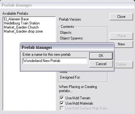
Naming your prefab
-
Click on the Create button to give your new prefab a name.
After selecting OK, the new prefab is created and can be used.
áá
Good luck!
===============================================================
Third Party Legal Information
===============================================================
Battlefield 1942 uses Bink Video
Technology.
Copyright ⌐ 1997-2000 by RAD Game
Tools, Inc.
===============================================================
DICE Copyright
===============================================================
Copyright ⌐ 2003 Digital Illusions
ALL RIGHTS RESERVED.
á