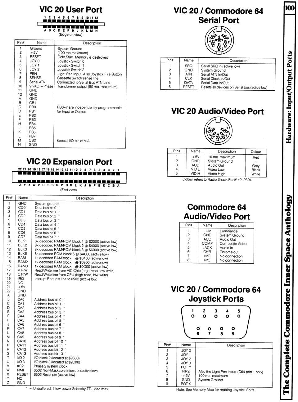
Labels:text | diagram | black and white | parallel OCR: VIC 20 User Port VIC 20 / Commodore 64 100 2 3 4 5 6 7 8 9 10 11 12 Serial Port ABCDEFHJKLMN (Edge-on view) Pin# Name Description 1 Ground System Ground 2 +5V (100 ma maximum) 3 RESET Cold Start. Memory is destroyed 4 JOY O Joystick Switch 0 Pin# Name Description 5 JOY 1 Joystick Switch 1 1 Joystick Switch 2 SRQ JOY 2 Serial SRO in (active low) 6 2 GND System Ground 7 8 PEN Light Pen Input. Also Joystick Fire Button 3 ATN Serial ATN In/Out SENSE Cassette Switch sense line 4 CLK Serial Clock In/Out 9 Serial ATN 56 10 9 VAC + Phase Connected to Serial Bus ATN Line Transformer output (50 ma maximum) DATA Serial Data In/Out RESET GND Resets all devices on Serial bus (active low) 11 12 GND A B GND CB1 C PB0 PBO-7 are independently programmable D PB1 VIC 20 Audio/Video Port E PB2 for Input or Ou ...