

The Camera Match utility uses a bitmap background photo and five special “CamPoint” objects to create or modify a camera so that its position, orientation, and field-of-view matches that of the camera that originally created the photo. This utility is primarily designed for architects and like professionals who need to create geometry that perfectly matches the photograph of existing structures.
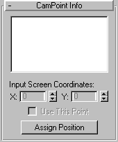
list window: Displays a list of the CamPoint helper objects in the scene. You select the CamPoint objects from this list to assign screen coordinate points. Note that if you select a CamPoint object in the viewport, it becomes selected in this list as well.
X/Y: Use these two spinners to fine-tune the position of the screen coordinate points in 2D space.
Use This Point: Lets you turn off a specific coordinate point without deleting it. Select the corresponding CamPoint in the list, and then uncheck Use This Point. This feature is typically used for troubleshooting when the Current Camera Error is too high (greater than 5, for example).
Assign Position: Click this button, and then click a location on the viewport bitmap to place a screen coordinate point visually against the background image. The point you place corresponds to the currently selected CamPoint object. The process is as follows: After activating the Assign Position button, you select a CamPoint object from the list, and then click in the viewport at a position on the bitmap background that corresponds with where the associate CamPoint object is supposed to be in the 3D scene. After repeating this process with each CamPoint object in the list, you can click the Create Camera button to create a camera that matches the placed coordinates with their associate CamPoint objects.
Current Camera Match: X/Y (text): After a camera is created, this displays the coordinates at which the camera projects the currently selected CamPoint to be. This should be close to the Input Screen Coordinates.
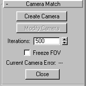
Create Camera: Click this to create a camera in the scene whose position, orientation, and FOV is based on the current location of the CamPoint helpers and the assigned screen coordinates points.
Modify Camera: Modify the position, orientation and FOV of an existing, selected camera based on the CamPoint helpers and assigned screen coordinates points.
Iterations: Maximum number of iterations used to calculate the camera position. Default is 500, though a stable solution is usually found in less than 100 iterations.
Freeze FOV: Click this to prevent the FOV (field of view) of the camera from being changed when using the Create Camera or Modify Camera buttons. Use this if the FOV of the camera that took the photograph is known, and you want to preserve it.
Current Camera Error: Displays the total error that remains between the placed screen coordinate points, the CamPoint helpers and the camera position after the final computation. The calculations involved in Camera Match are seldom, if ever perfect. However, a good error range is in the area of 0-1.5. If you’re over 10, however, one of your points is way off.
Close: Click this to exit the Camera Match utility.
The following exercise shows how to set up a camera to match the perspective view of a bitmap background. It requires the file cmlib.jpg, which is not really a photograph, but you can use your imagination.
Tip: You can see the resolution of any bitmap by first viewing it using File/View File, and then right-clicking over the image in the Virtual Frame Buffer.
The viewport displays a row of shelves.
Next, create five CamPoint helper objects, using Keyboard Entry to place them in pre-defined 3D coordinates that match those of the real shelves. (The bitmap image is of a 3D model based on a real set of shelves. To do this in reality, you would need to know specific coordinates for the actual structure.) The following list provides suggested, descriptive object names along with each object’s 3D coordinates.
Object Name Coordinates
1st shelf, Left-Front 0, 0, 0
1st shelf, Left-Back 0, 11.2, 0
3rd shelf, Left-Front 0, 0, 24
3rd shelf, Left-Back 0, 11.2, 24
5th shelf, Left-Front 0, 0, 48
5th shelf, Right-Front 31, 0, 48
Tip: To use the keyboard, first click in the X field, enter its value, then press Tab to move to the next field and enter its value. Continue this until you tab to the Create button, then press Enter to create the CamPoint, followed by Tab to move back to the X field, where you can start again. You can create all six objects with default names, and then use the Select by Name floater (Tools/Selection Floater) to select and rename the six pointers.
Note: An alternative method is to create the CamPoint objects anywhere in the scene, and then reselect each of them and enter their absolute coordinates using the Transform Type-In dialog.
You now have six point objects occupying real-world coordinate positions that correspond to the structure in the bitmap image. The last sequences of steps is to use the Camera Match utility to specify six screen coordinate pointsone for each CamPoint objectand generate a camera position based on the data.
The Camera Match utility appears, listing the CamPoint objects in its list window.
A small red cross appears where you clicked.
The second dot is placed at the back-left corner of the same shelf. The third and fourth points are placed in the equivalent positions, but on the third shelf from the bottom, and the fifth and sixth points are placed on the front two corners of the fifth shelf.
A camera is created in the scene based on the location of the CamPoint objects and the specifications of the screen coordinates points.
Note: If the Current Camera Error reading is greater than 5, at least one of your screen coordinate points is placed wrong. Double-check each of them, and take another look the description following step 5. After reassigning the points, select the existing camera, and click the Modify Camera button to recalculate the camera position.