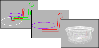


Spline shapes, Path shape created, Lofted shape in wireframe
Loft objects are two dimensional shapes extruded along a third axis. You create loft objects by creating two or more spline objects. One of these splines will be the path. The rest of the splines are the cross sections of your object which are called shapes. As you arrange your shapes along the path, 3DS MAX generates a surface between the shapes.
If there is only one shape on the path, 3DS MAX assumes an identical shape is located at each end of the path. The surface is then generated between the shapes.
3D Studio MAX places few restrictions on how you create your loft object, unlike the traditional shipbuilding and model-building examples above. Using 3DS MAX you can create curved, three-dimensional paths and even three-dimensional cross sections.
You create shape objects to serve as a path for any number of cross-section shapes. The path becomes the framework that holds the cross sections forming your object.
Once you create a loft object you can change and animate its parameters and sub-objects:
The lofting process first requires that you create shape objects to serve as the path and cross sections of your loft object.
Creating loft objects is detailed and offers many choices, but the basic process is quite simple. The basic process for creating a loft object is as follows:
You can use the loft display settings to view the skin generated by your loft in both wireframe and shaded views.

Creating loft objects is detailed and offers many choices, but the basic process is quite simple.
Get Path: Assigns a path to the selected shape or changes the current assigned path.
Get Path is located in the Creation Method rollout with Get Shape. The rollout has three options that control what happens to the shape you get as a path:
Move: The path shape becomes part of the loft and no longer exists as an object in the scene.
Copy: A copy of the path shape is used in the loft object. The original shape and the copy in the loft are independent. Changing one has no effect on the other.
Instance: An instance of the path shape is used in the loft. The original shape and the instance represent the same object. Changing one also changes the other.
Tip: You might find it easier to use the Instance option if you expect to edit or modify the path after the loft is created.
Get Shape: Selects a path shape and then place a cross section on the path. You can also use Get Shape to add or replace shapes along a loft object's path.
Get Shape is located in the Creation Method rollout with Get Path. The rollout has three options that control what happens to the shape you get as a path:
Move: The shape becomes part of the loft and no longer exists as an object in the scene.
Copy: A copy of the shape is used in the loft object. The original shape and the copy in the loft are independent. Changing one has no effect on the other.
Instance: An instance of the shape is used in the loft. The original shape and the instance represent the same object. Changing one also changes the other.
Tip: You might find it easier to use the Instance option if you expect to edit or modify the shapes after the loft is created.

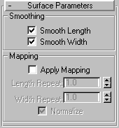
Smooth Length: Check Smooth Length when you want a smooth surface along the length of the path. This type of smoothing is useful when your path curves or when shapes on the path change size. Default=selected
Smooth Width: Check Smooth Width when you want a smooth surface around the perimeter of the cross-section shapes. This type of smoothing is useful when your shapes change the number of vertices or change form. Default=selected
Apply Mapping: Toggles the application on lofted mapping coordinates on and off. Apply Mapping must be checked before you can access the remaining items.
Length Repeat: Sets how many times a map repeats along the length of the path. The bottom of the map is placed at the first vertex of the path.
Width Repeat: Sets how many times a map repeats around the perimeter of cross-section shapes. The left edge of a map is aligned with the first vertex of each shape.
Normalize: Toggles how path vertex spacing affects a map along both the path length and shape width. When checked, vertices are ignored. Map coordinates and Repeat values are applied evenly along the length of the path and around the shapes.
When unchecked, major path divisions and shape vertex spacing affects map coordinate spacing. Map coordinates and Repeat values are applied proportionally according to the path division spacing or shape vertex spacing.

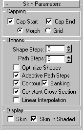
Cap Start: When selected, the end of a loft at the first vertex of the path is covered, or capped. When unchecked, the end is open, or uncapped. Default=selected.
Cap End: When selected, the end of a loft at the last vertex of the path is covered, or capped. When unchecked, the end is open, or uncapped. Default=selected.
Morph: When selected, cap faces are arranged in a predictable, repeatable pattern necessary for creating morph targets. Morph capping can generate long, thin faces that do not render or deform as well as those created with grid capping.
Grid: When selected, cap faces are arranged in a rectangular grid trimmed at the shape boundaries. This method produces a surface of evenly sized faces that can be easily deformed by other modifiers.
Shape Steps: Sets the number of steps between each vertex of the cross section shapes. This value affects the number of sides around the perimeter of the loft.
Path Steps: Sets the number of steps between each main division of the path. This value affects the number of segments along the length of the loft.
Optimize Shapes: When selected, the Shape Steps setting is ignored for straight segments of cross-section shapes. If multiple shapes are on the path, only straight segments that have a match on all shapes get optimized. Default=clear.
Adaptive Path Steps: When checked, Adaptive Path Steps is turned on. 3D Studio MAX analyzes your loft and adapts the number of path divisions to generate the best skin. Main divisions along the path occur at path vertices. shape locations, and deformation curve vertices. Whenclear, Adaptive Path Steps is turned off, and main divisions along the path only occur at path vertices. Default=selected
Contour: When selected, each shape follows the curvature of the path. The positive Z axis of each shape is aligned with the tangent to the path at the shape's level. When clear, all shapes remain parallel and have the same orientation as a shape placed at level 0. Default=selected.
Banking: When selected, shapes rotate about the path whenever the path bends and changes height in the path's local Z axis. The bank amount is controlled automatically by 3DS MAX. Banking is ignored if the path is 2D. When clear, shapes do not rotate about their Z axis as they traverse a 3D path. Default=selected.
Constant Cross Section: When selected, the cross-sections are scaled at angles in the path to maintain uniform path width. When this is clear, the cross sections maintain their original local dimensions, which causes pinching at path angles.
Linear Interpolation : When selected, generates a loft skin with straight edges between each shape. When clear, generates a loft skin with smooth curves between each shape. Default=clear.
Skin: When selected, displays a loft's skin in all views using any shading level. When Skin is checked the setting of Skin in Shaded is ignored. When unchecked, displays only the loft sub-objects. Default=clear.
Skin in Shaded: When selected, always displays a loft's skin in shaded views regardless of the Skin setting. When unchecked, skin display is controlled by the Skin setting. Default=selected.

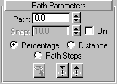
Path: Use the Path field to set a path level by entering a value or dragging the spinner. If Snap is on, the value will jump to the previous snap increment. The Path value depends on the selected measuring method. Changing the measuring method causes the Path value to change.
Snap: Enter a snap-spacing value in the field. The Snap value depends on the selected measuring method. Changing the measuring method also changes the Snap value to keep snap spacing constant.
On: When selected, Snap is active. Default is clear
Percentage: Expresses the path level as a percentage of the total path length.
Distance: Expresses the path level as an absolute distance from the first vertex of the path.
Path Steps: When this option is chosen, shapes are placed on path steps and vertices, rather than as a percentage or a distance along the path.
When Path Steps is chosen, the following takes place:
Caution: Please note the following when using the Path Steps option:
Pick Shape: Click this button to set the current level at any shape on the path. When you pick a shape on the path, Snap is turned off and Path is set to the level of the picked shape. The pick shape highlights in green.
Use the Previous Shape and Next Shape buttons to jump the current level to the previous or next shape on the path, highlighting the shape in green. Clicking these button also turns Snap off.
Previous Shape: Jumps the path level from its current location to the previous shape along the path.
Next Shape: Jumps the path level from its current location to the next shape along the path.
The cursor changes to the Get Path cursor as you drag it over potential valid path shapes. If the cursor does not change over a shape, that shape is not a valid path shape and cannot be selected. The first vertex of the selected path is placed at the first shape's pivot and the path tangent is aligned with the shape's local Z axis.
If the selected shape is not a valid path, the Get Shape button will be disabled.
The cursor changes to the Get Shape cursor as you drag it over potential shapes. The selected shape is placed at the first vertex of the path.
#ENDNUMBLOCK#