

ShapeMerge creates a compound object consisting of a mesh object and one or more shapes. The chosen shapes are either embedded in the mesh, altering the edge and face patterns, or subtracted from the mesh.

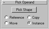
Pick Shape: Click this button, and then click the shape you want embedded in the mesh object. The shape is projected onto the mesh object in the direction of the shape’s local negative Z axis. For example, if you create a box, and then create a shape in the Top viewport, the shape is projected onto the top of the box. Note that you can repeat this process to add additional shapes, and the shapes can be projected in different directions. Just click Pick Shape again, and then pick another shape.
Reference/Copy/Move/Instance: These options specify how the shape is transferred to the compound object. It can be transferred either as a reference, a copy, an instance, or moved, in which case the original shape is not left behind.

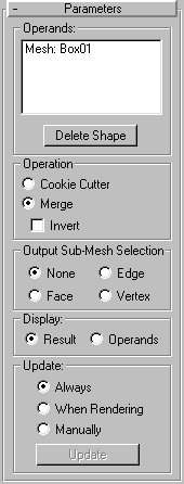
List field: Lists all the operands in the compound object. The first operand is the mesh object, and there can follow any number of shape-based operands
Delete Shape: Select one or more of the shapes in the list window, and click Delete Shape to remove the selection from the compound object.
The options in this area determine how the shape is applied to the mesh.
Cookie Cutter: Cuts the shape out of the mesh object’s surface.
Merge: Merges the shape with the surface of the mesh object.
Invert: Reverses the effect of either Cookie Cutter or Merge. With the Cookie Cutter option, the effect is obvious. Unchecked, the shape is a hole in the mesh object, and checked, the shape is solid and the mesh is missing. When you’re using Merge, Invert reverses the sub-object mesh selection. As an example, if you merge a circle shape, and apply a Face Extrude, the circular area is extruded when Invert is not checked, and all but the circular area is extruded when Invert is checked.
Provides options that let you specify what selection level is passed up the Stack. Note that the ShapeMerge object stores all selection levels. That is, the vertices, faces, and edges of the merged shape are all stored with the object. (If you apply a Mesh Select modifier and go to the various sub-object levels, you’ll see the merged shape is selected.) Thus, if you follow the ShapeMerge with a modifier that acts on a specific level, such as Face Extrude, that modifier will work properly. However, if you apply a modifier that can work on any selection level, such as Volume Select or Xform, the options here will specify which selection level is passed to that modifier. Note also that, although you can use a Mesh Select modifier to specify a selection level, the Mesh Select modifier only considers the selection at frame 0. Thus, if you’ve animated the shape operand, that animation will only be passed up the Stack for all frames by use of the Output Sub-Mesh Selection options.
None: Check this to output the full object.
Edge: Outputs the edge of the merged shape.
Vertex: Outputs the vertices defined by the spline of the shape.
Face: Outputs the faces within the merged shape.
Determines whether or not the shape operands are displayed.
Result: Displays the result of the operation
Operands: Displays the operands.
These options specify when the display of the merge is updated. Typically, these are used when you’ve animated the merged shape operands and it’s slowing down the viewport display.
Always: Update the display at all times.
When Rendering: Update the display only when the scene is rendered.
Manually: Update the display only when the Update button is pushed.
Update: Use this to update the display when any option except Always is chosen.
The geometry of the surface of the mesh object is altered to embed a pattern matching that of the selected shape.