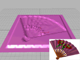


Reshapes geometry with a variable force that can be applied directly from the modifier gizmo or from a bitmapped image.
The Displace Modifier acts as a force field to push and reshape an objects geometry. This is a very versatile modifier with many possible applications. These are two basic ways to use it:

Displace warp on a patch and the bitmap it uses
The Displace Space Warp has similar features. It is useful for applying effects to a large number of objects or a particle system.
Displace gives you the option of applying the gray scale of a bitmap image to control displacement. Lighter colors in the 2D image push outward more strongly than darker colors, resulting in a 3D displacement of the geometry.
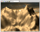
Terrain effects using displace
The gizmos of the Displace modifier carry the force field that displaces geometry. By rotating, scaling, and moving one of these gizmos, you can effectively model geometry.
The Spherical and Shrink Wrap gizmos begin with a uniform field around them. The Cylinder and Planar gizmos are both directional. Cylinder pushes at right angles to its axis, and Planar pushes at right angles to its surface.
In the following figures, the Spherical gizmo is scaled down and squashed into a pointed tool, then moved to deform the geometry of a sphere. At low strength, the effect is like pushing a rubbery material with a shaped stick. As strength goes up, the effect is massive displacement of the geometry. The following procedural steps are generic to any gizmo.
Experimentation is the key to displacement modeling. Here are some options to consider:
Displace distributes its force through four different gizmos: Planar, Cylindrical, Spherical, and Shrink Wrap.
By default, gizmos are centered on the object. However, any of these shapes can be transformed and used directly as a tool to deform the geometry of an object.
Gizmos are also used as mapping coordinates for applying bitmaps. Sphere and Shrink Wrap have the same effect when modeling, but differ in the way they map.
A new option in the Displace modifier lets you specify the center of luminance in the bitmap that’s displacing the geometry. Previously, Displace assumed a 0.5 value, which meant that any grayscale value above 0.5 was displaced in one direction, while values below 0.5 were displaced in the other.
To use this option, check Luminance Center, and then adjust the Center spinner. When using a Planar projection method, the result is a repositioning of the displaced geometry above or below the planar gizmo. (Spinner Value: float, 0 to 1)
Note: This option has also been added to the Displace space warp, which is not explicitly documented here.
New Length, Width, and Height spinners in the Map area let you specify the dimensions of the map.
In the Alignment area are new X, Y, and Z option buttons that let you flip the alignment of the mapping gizmo.
The View Align and Region Fit buttons have been added to the Displace modifier.
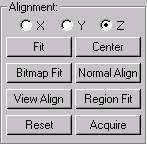
The Alignment area contains controls for adjusting the mapping gizmos size, position, and orientation.
Cylindrical Capping
A Cap checkbox has been added beside the Cylindrical mapping method. This works the same as the Cap option in the UVW Map modifier, in that it projects a copy of the map on the cylinder’s caps.
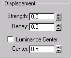
To create the force field that surrounds a Displace gizmo, you vary two interrelated parameters, Strength and Decay.
Strength: When set to 0, Displace has no effect. Strength greater than zero displaces object geometry away from the position of the gizmo. Strength less than zero displaces geometry toward the gizmo. Default=0.
Decay: When set to 0, Displace has the same strength throughout object space. Default=0. Increasing the Decay value diminishes the field strength as distance increases from the gizmo. This has the effect of concentrating the force field near the gizmo, similar to the field around a magnet repelling its opposite charge.
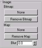
??? Note, the screen capture does not match the UI description.
You can now assign a map (as compared to a bitmap) to the Displace modifier. The Image area now has four buttons instead of two. The original two bitmap assignment and Remove Bitmap buttons work as before, and lets you directly assign a bitmap.
Under the label “Map” are two additional buttons. The first is the assignment button, and it works the same as the Environment and spotlight map buttons. Click it to display the Browser, from which you can choose a map, or simply drag a map from the Browser over the assignment button. A Remove Map button lets you remove the map entirely from the Displace modifier.
The following controls in the Displacement area are used with bitmaps.
Center Luminance: Automatically 'centers' the luminance by using medium (50%) gray as the zero displacement value. Gray values greater than 128 displace in the outward direction (away from the gizmo) and gray values less than 128 displace in the inward direction (toward the gizmo).
Image: Assigns a bitmap to create the displacement pattern. After you choose a bitmap, this button displays the bitmap's name.
Remove Image: Removes the bitmap assignment.
Blur: Blurs or softens the effect of the bitmapped displacement with values above 0.
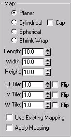
This area contains mapping parameters for bitmapped displacement. Their use is summarized here. See UVW Map Modifier for details on using the UVW map modifier.
The four mapping modes control how Displace projects its displacement. The type of Displace gizmo and its location in the scene determine the final effect.
Planar: Projects the map from a single plane, somewhat like projecting a slide.
Cylindrical: Projects the map as if it were wrapped around the cylinder.
Spherical: Projects the map from a sphere, with singularities at the top and bottom of the sphere, where the bitmap edges meet at the sphere's poles.
Shrink Wrap: Projects the map from a sphere, as Spherical does, but truncates the corners of the map and joins them all at a single pole, creating only one singularity at the bottom.
UVW Tile: Sets the number of times the bitmap repeats along the specified dimension. A value of 1.0, the default, maps the bitmap exactly once; a value of 2.0 maps the bitmap twice, and so on. Fractional values map a fractional portion of the bitmap in addition to copies of the whole map. For example, a value of 2.5 maps the bitmap two and a half times.
Flip: When checked, reverses the orientation of the map along the corresponding U, V, or W axis.
Use Existing Mapping: Set on to have the displace warp use the UV mapping of the bound object. Has no effect if the bound object is not mapped.
Apply Mapping: Set on to apply the displace warp's UV mapping to the bound object. This lets you apply material maps to the object using the same mapping coordinates the displace warp uses.
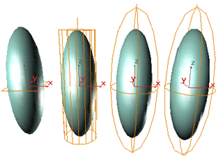
Displace Gizmos
This Parameters rollout appears.
As you vary these settings, you see the effect of displacement on the object.
Depending on the object and the complexity of the bitmap, you might need to use dense geometry to see the effect clearly. Try a test run and, if necessary, add tessellation in the areas of greatest detail.
The following bitmap was used to create the example in this topic.
Increase the strength of the field to see the effect of the bitmap displacing the object's geometry.
After you get the image you want from bitmapped displacement, you can apply an Optimize modifier to reduce the complexity of the geometry.